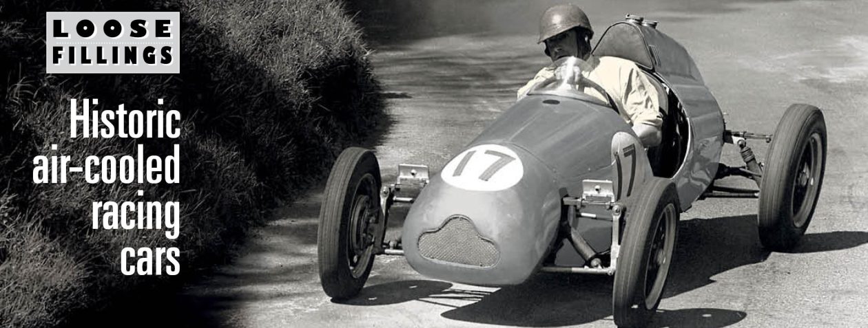
Terry Wright records his experiences restoring, hillclimbing
and developing Bruce Walton’s two great JAP-engined hillclimb cars over the last 30 or so years. On another page there is a detailed list with two cars shown for sale, several complete engines and many spares.
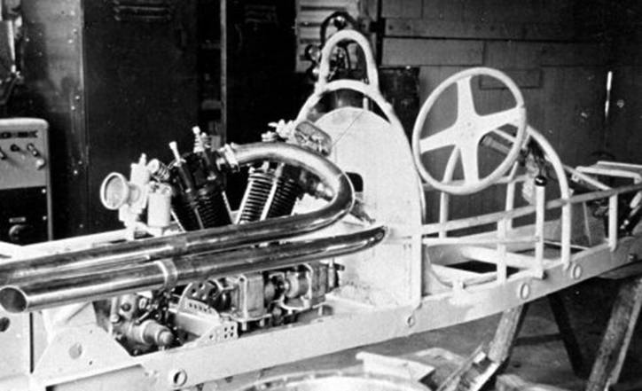
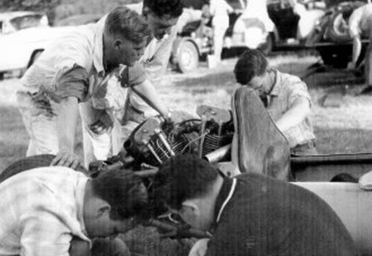
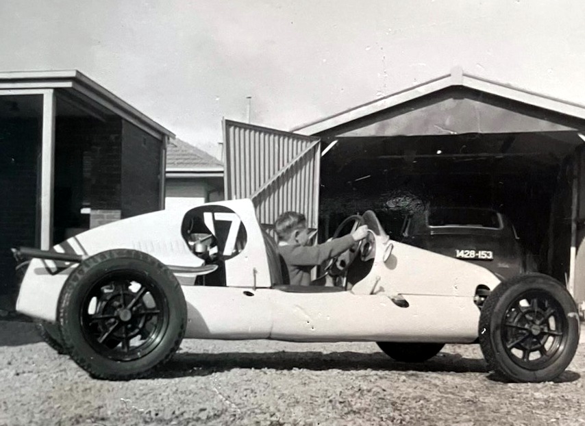
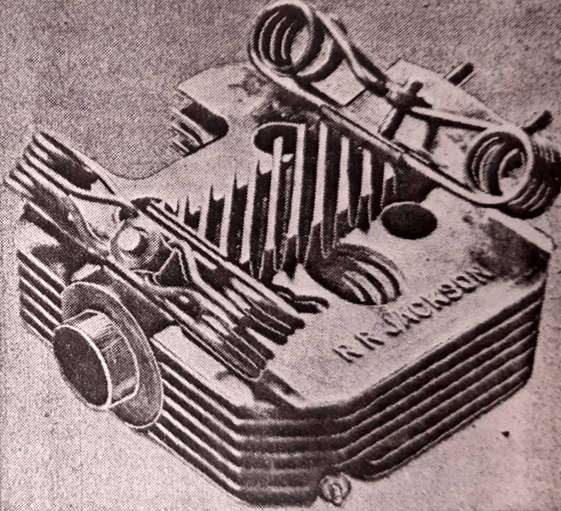
The Walton JAP under construction in Ken Gayfer’s Melbourne garage about 1952. The 996cc 8-80 JAP twin had iron heads and barrels. The engine is believed to have come from a crashed Cooper.
Bruce Walton was Australia’s longest-reigning hillclimb champion from 1958. After taking a science degree at the University of Adelaide, he moved to Melbourne in the early nineteen-fifties to work in the laboratories of the new Gas and Fuel Corporation.
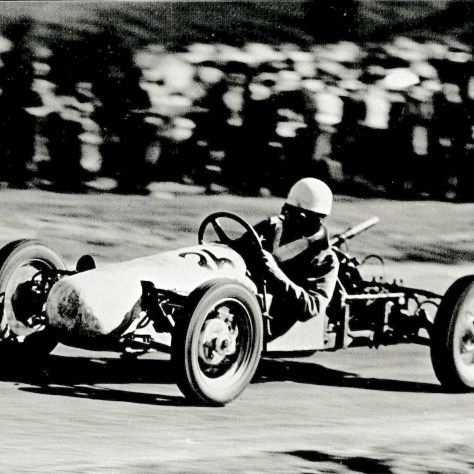
With a 498cc JAP speedway engine Bruce Walton soon came to grips with his new special.
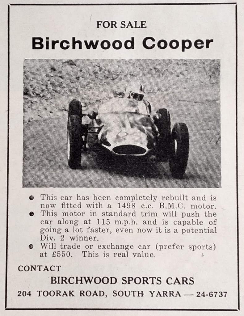
As many did then, Bruce took a keen interest in the new ‘500’ car movement, and set about building a Cooper likeness. An 8-80 twin JAP from a crashed Cooper was his brave choice of engine. This first car, the ‘Walton JAP’, made its competition debut on 18 July 1953. Bruce soon decided to run a more manageable and reliable 498cc single-cylinder JAP engine and with this he drove better and better. There was a third at Fishermans Bend races, a class win and third fastest-time of-day at Collingrove hillclimb, a first racing at Altona and class records at Rob Roy and Templestowe hillclimbs
The 8-80 JAP went back in for 1956 and there followed class and meeting wins around Australia including at Newcastle for the NSW Championship which he won, and Bathurst for the Australian Championship when he was second to Lex Davison’s Cooper Vincent tuned by Phil Irving.
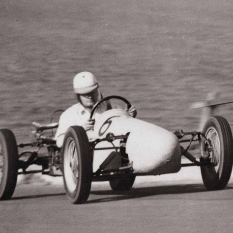
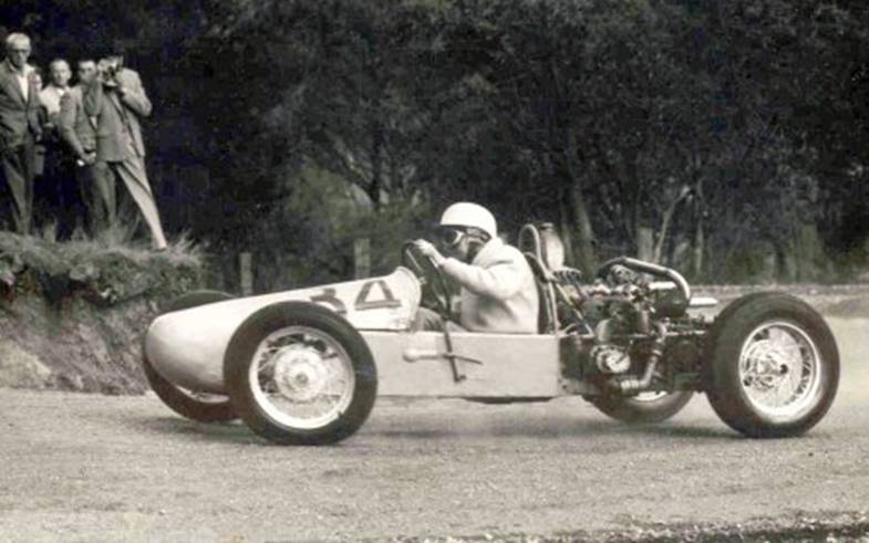
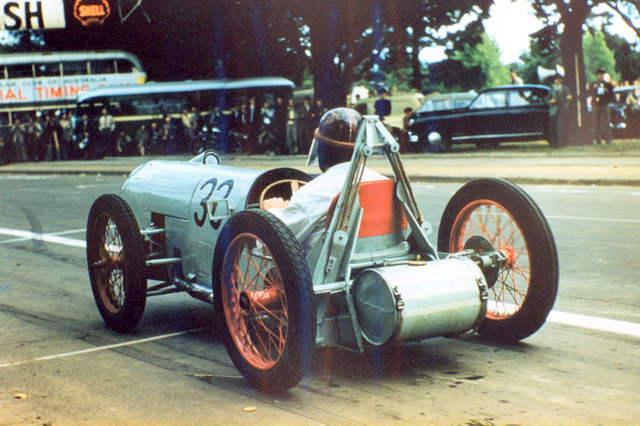
Above, when the 996cc 8-80 JAP twin engine was reinstalled, Bruce won the NSW championship at Newcastle in 1956.
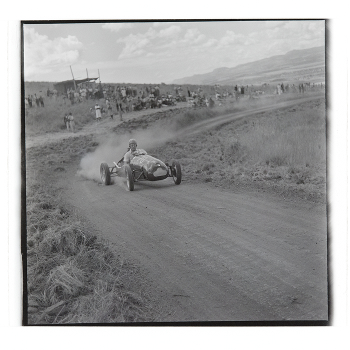
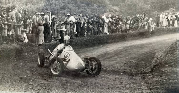
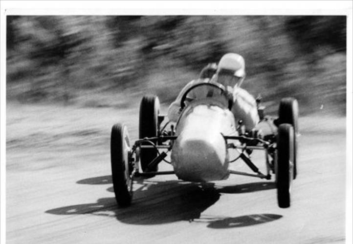
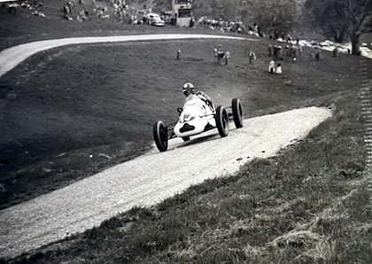
Above: Bruce in the Walton JAP flying at Rob Roy, date unknown, Peter Dabbs photo. Below: with an ex RAAF Marshall cabin blower as a supercharger Bruce took the Victorian hillclimb championship in 1957 as below at Hepburn Springs, Victoria.
With a supercharged 1098cc Mk1 V-twin JAP next installed, Bruce finally beat the Davison Cooper over the closely fought three rounds of the Victorian Hillclimb Championship in 1957. In the final round at Rob Roy on 5 November, if Lex made fastest-time-of day (FTD) then the title would be his; if Bruce made FTD it would be a tie and he would win the title only if he got the bonus point for a new hill record. Lex’ last run was a new record at 24.44sec; Bruce made a final dash of the day in a new record … 24.40sec! The title was his at last.
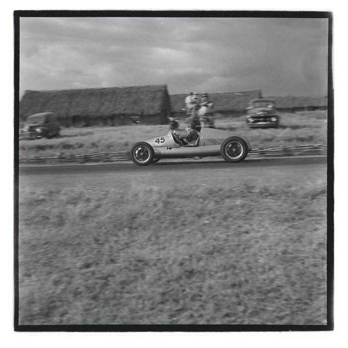
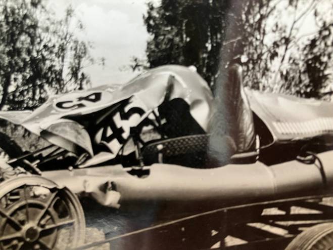
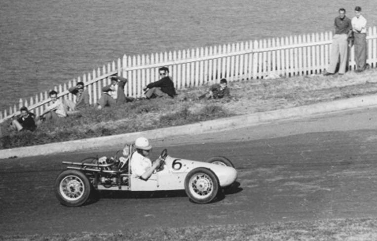
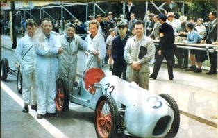
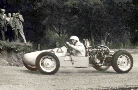
Roy Blake in the Mk8 Cooper which he jointly owned with Steve de Bord. He came second to Bruce at Newcastle hillclimb in 1956 and is here at Forrest’s Elbow at Bathurst for the 1957 Australian hillclimb titles. Bruce Walton bought the car and installed a JAP twin and blower.
When he had won the New South Wales Hillclimb Championships at King Edward Park in Newcastle in 1956, Walton had found some unexpectedly close competition from a car of only half his engine capacity. It was a Mk 8 Cooper-JAP 500 driven by Steve de Bord who was just two-tenths of a second behind Bruce and second overall.
Lex Davison had been urging Walton to ‘get a proper racing car’ (or words to that effect) and Bruce bought the de Bord/Blake Cooper – chassis Mk8-33-58 – late in 1957 into which went the big JAP engine and the Marshall cabin-blower supercharger from the Walton-JAP. The first outing of the ‘Walton Cooper’ as such was in July 1958 at Rob Roy but Bruce’s best time was only 26.24 seconds, compared with the outright record of 24.15 seconds which he had set with the Walton JAP a month earlier.
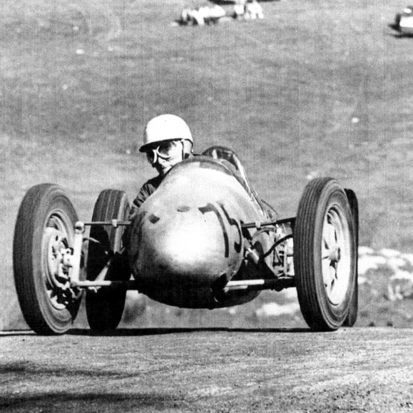
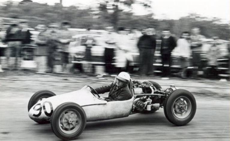
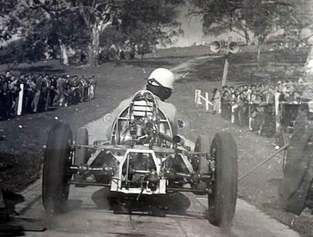
Above, Bruce and the Mk8 Walton Cooper breasts the hill at Templestowe, north of Melbourne. Below, he tips the car into the first corner at Templestowe.
Walton found the Cooper had excessive understeer and serious
instability at speed over the bumps that were then the norm at hillclimbs. Sorting it out took nearly two years of experimentation with Bruce’s wife Camille crouched trackside to film the car’s antics on 8mm film for later analysis. The film was to show a bucking, bouncing, beast of a car.
Above, Bruce leaves the start line at Silverdale west of Sydney and, below, takes a precise line at Bigtree.

Eventually, by flattening the front springing and modifying the sticking splines in the drive-shafts, the car was tamed. In 74 hillclimbs with the Cooper, Bruce Walton set 17 outright records, 69 fastest times of day and had an Australian Guinness Book of Records entry for the most successive sporting titles – six Australian Hillclimb Championships from 1958 to 1963 – and many state titles.
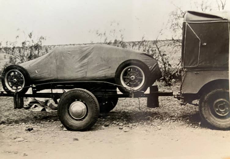
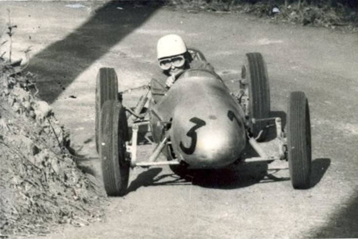
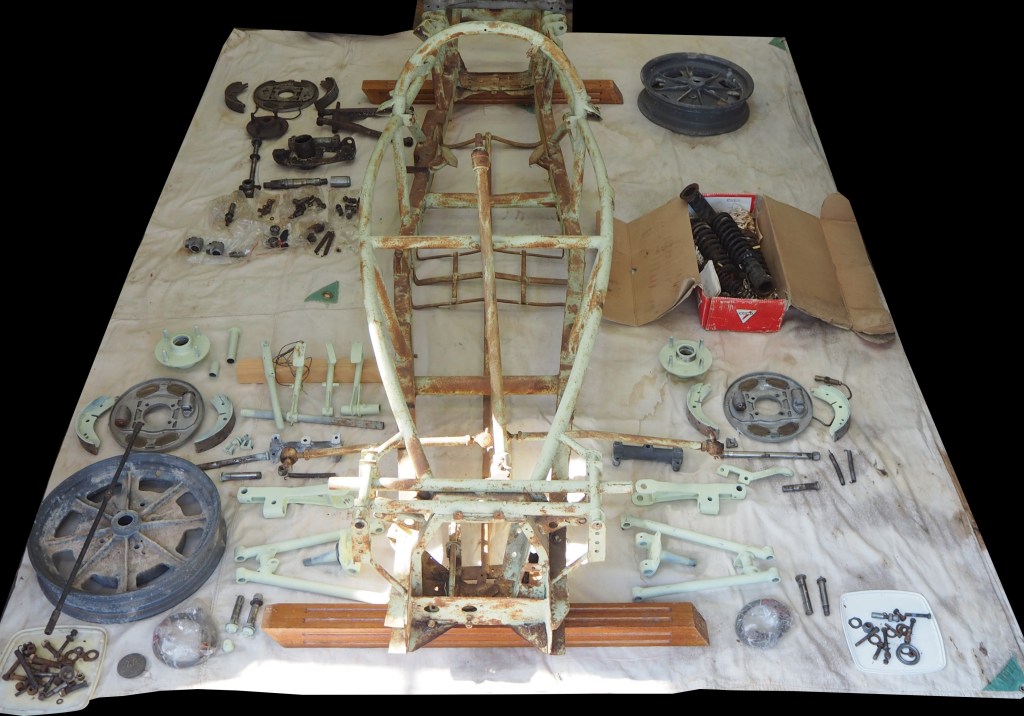
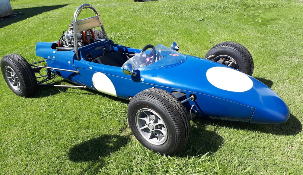
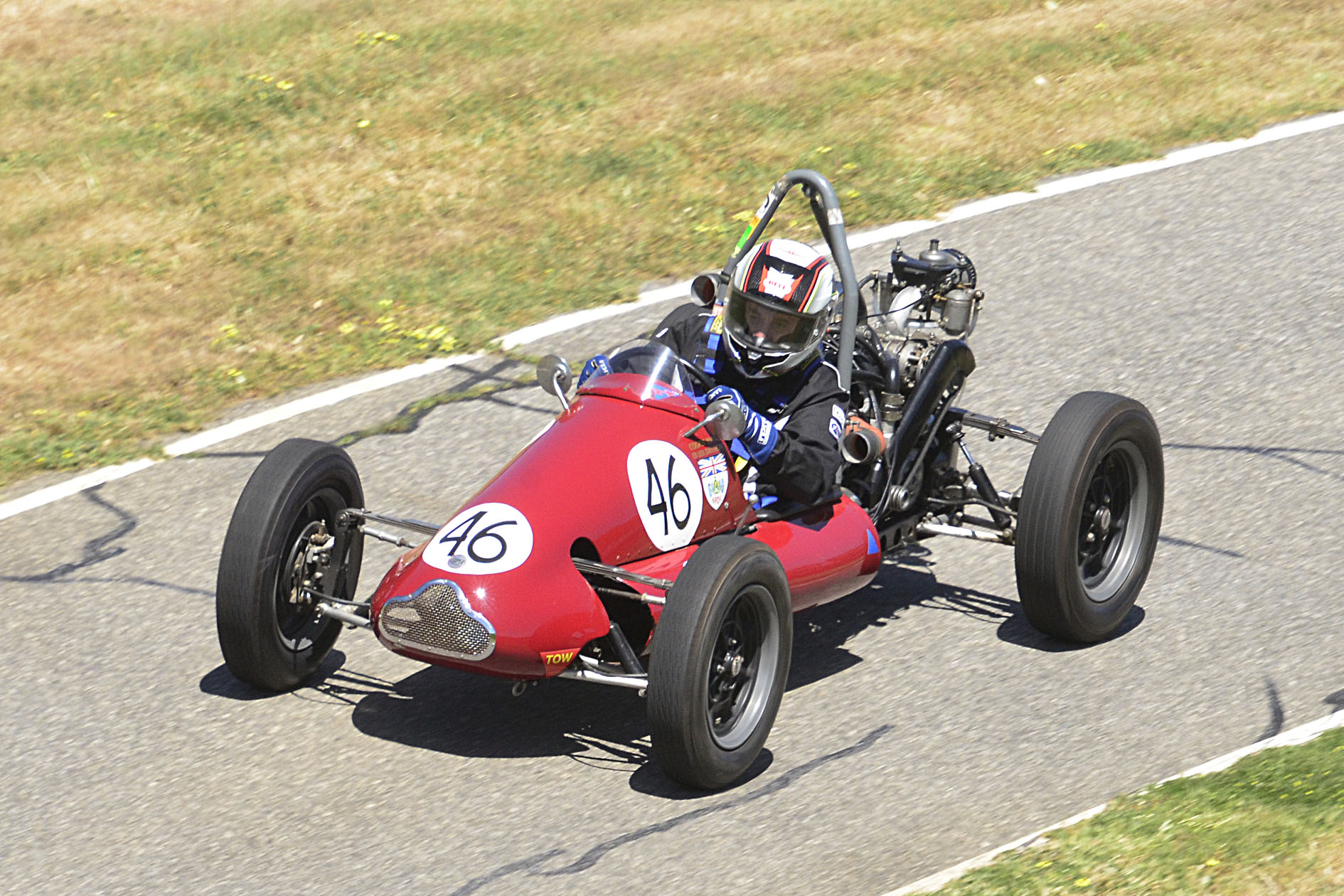
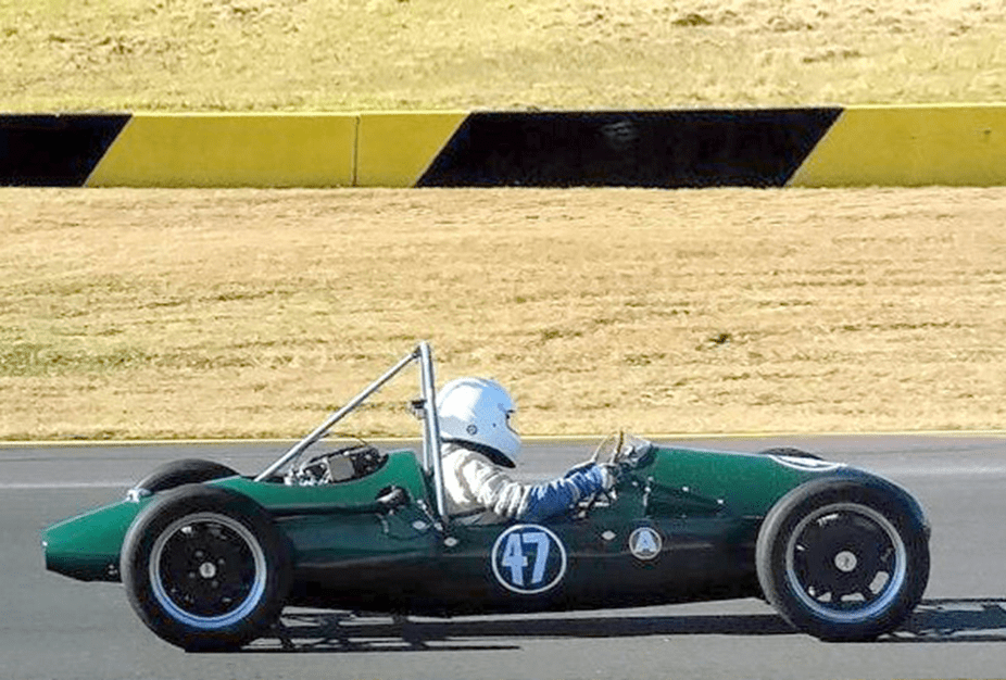
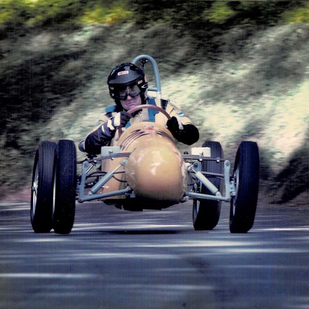
The Walton JAP (below, restored) had passed through many hands when I bought it from Victoria’s David Rapley in 1994. In Sydney the chassis restoration was completed by Garry Simkin and a 1098cc Mk1 JAP twin was installed. In this form the car was tested in Australia at Newcastle and Rob Roy hillclimbs and then shipped to the UK where it competed for several years in most of the major hillclimbs including Shelsley Walsh, Loton Park, Eagles Rock, Gurston Down, Prescott, Wiscombe Park, Craigantlet and Bo’ness.

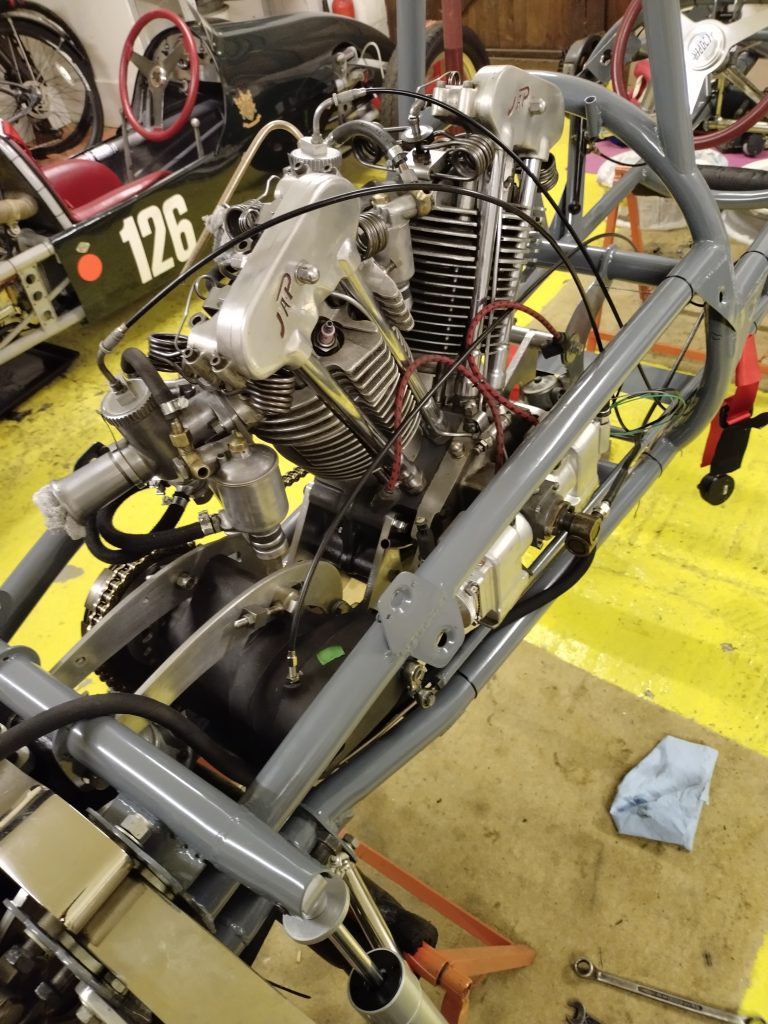
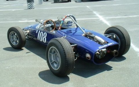
The Walton JAP today with a new 8-80 JAP as originally used by Bruce Walton with a starter motor in the place of his supercharger. The starter is normally masked by a dummy fuel tank. Ignition is electronic using Harley Davidson components in Lucas magneto shells. There is a two-into-one modern silencer and twin 1.5in GP Amals supplied by an electric fuel pump.
The longest haul was to the classic Ollon-Villars in Switzerland and with an 8 kilometre mountain climb it was an awesome experience. Eventually the Walton JAP returned to Australia and competed at Newcastle, Bathurst and Collingrove hillclimbs before undergoing major engine development. A replica 8-80 type JAP engine was manufactured with a new pressed-up crankshaft by Greg Summerton, thus returning the car to the form in which Bruce Walton first used it.
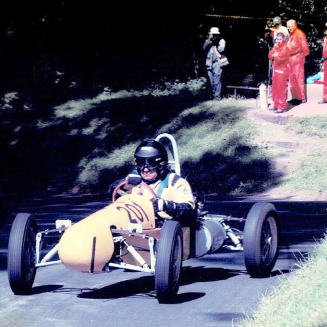
Above, into Top Ess at Shelsley Walsh and, below, overdoing it a shade on the exit.
When I had finished restoring the Walton JAP and started to get the hang of it, I had gone looking for the Walton Cooper about 2000. I already knew that after passing through several hands in Melbourne after Bruce had retired from competition in 1963 it had eventually been sold to a new owner in Perth, Western Australia. He had died sometime in the mid-seventies but I tracked down his widow and she told me who had bought the car after her husband’s death.
Just one more phone call confirmed the Cooper’s presence in the lobster fishing town of Geraldton far north of Perth and so a long way from Sydney. I went to see it and late in 2002, after over a year of quiet negotiation, the car was purchased, crated, and trucked back across Australia to Sydney where a complete restoration soon commenced.
Restoration was completed just in time for the car to be shipped to the UK for the centenary meeting at Shelsley Walsh in August 2005; there it won its class with a time of 37.12 seconds. Subsequently my best time there was 35.54 seconds and I was most happy with that because the best Cooper time I know of was David-Boshier Jones’ hill outright record of 35.47 seconds in 1959 although he was without supercharging which may or may not have been a help.
The Shelsley Walsh farmyard start, above, and drifting into Bottom Ess, below.
After more seasons on the UK hills the Walton Cooper returned to Australia where I concentrated on building a new engine for the Walton JAP as mentioned above. But the long break in motorsport because of Covid then diverted my attention in other directions and I have climbed my last hill. Bruce’s cars, however, are ready for plenty more.
Addendum
David Boshier-Jones, many times British Champion, exits Top Ess at Shelsley Walsh – a good speed through here onto the finishing straight was essential for a good time.