It is Higher School Certificate (HSC) exam time for year 12 high school students in Australia. Poor kids, including the editor’s grandson, have had to cope with a year in which practical work and engagement with teachers – which could make or break some of them – has been made very difficult. We wonder how they would cope with the following question from the last year’s Engines – JAP Racing –Maintenance examination as imagined by Steve Denner:
Introduction
A V-twin, 4 stroke engine has the cylinders disposed at 50°. The connecting rods run on a common journal. A half-timing pinion (HTP) has 18 teeth and runs on the end of the mainshaft, i.e. at engine speed, and clockwise viewed from the outside of the timing chest. The HTP drives the 36 tooth cam gear for No.2 cylinder, and this in turn drives the cam gear for No.1 cylinder.
The mainshaft carries a key to locate the HTP, and the HTP has five equally separated keyway options for adjusting the valve timing.
Question
The current valve timing opens the inlet valves at 38 degrees BTDC.
Write the paragraph for the Owner’s Manual which will describe the
procedure for
1. Advancing the valve timing by 4 degrees
2. Retarding the valve timing by 8 degrees.
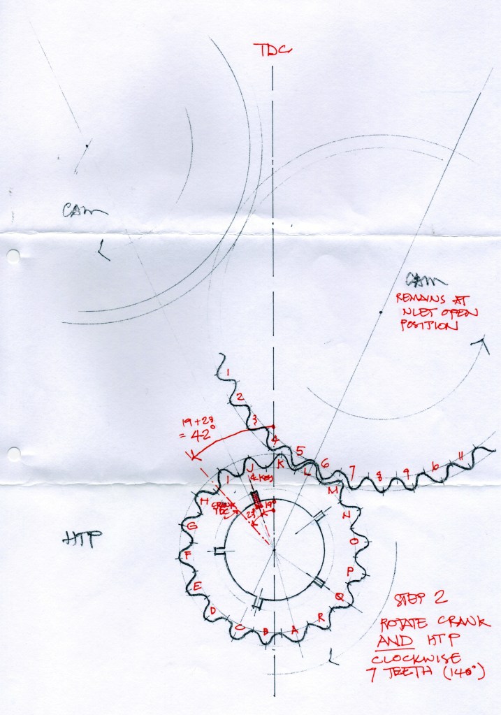
Steve has reported on last year’s answers and has added some useful drawings. Most candidates worked out that the arrangement of 5 keyways and 18 teeth is essentially a vernier coupling. That is, there are 5×18 (90) different positions that the half time pinion can be engaged with the cam gear. Dividing 360° by 90 means each position offers a 4° degree variation.
It is essential to start from the existing and known valve timing by marking the current engagement of pinion and cam teeth, and also the currently utilized keyway in the pinion.

STEP 1 requires the pinion to be disengaged from the crank with the cam gears held in position, and the crank rotated anti-clockwise and
re-engaged in a new key position as dictated by the required degrees of advance or retard (see table below).

STEP 2 requires both the crank and pinion to be rotated clockwise by the number of teeth indicated in the table, and the pinion to be
re-engaged with the cam gear teeth that were marked at the outset.
Condensed into a tabular form it looks as follows. The degree of advance or retard achieved is the difference between Columns 1 and 5.

The first response was from Mark Burns who eats lots of fish, does The Times crossword before breakfast, and consequently has a brain the size of a small planet. He also produced the drawings to support his solution. Planning permission has been applied for and many thanks, Mark.
Curiously no response was forthcoming from any Morgan Three-wheeler owners. Perhaps a cold chisel and 2lb lump hammer is all that is required to keep them running?
The author thanks all participants and thanks them collectively for saving him the trouble of exercising his own strained grey matter, and hours of random and pointless meddling on the workshop bench.
Stephen Denner
The editor is also most grateful, being about to re-time the Walton JAP engine that shed some cam gear teeth just in time not to make the Collingrove hillclimb a year ago.
