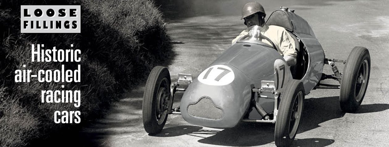
by Steve Denner
Many moons ago Chas McGurk confided to Demon Tweaks that it was possible to convert the V-twin JAP to a simple coil and distributor (Kettering) system by mounting and driving a distributor in place of one of the magnetos.
In one such conversion Chas had crept up on an unsuspecting Vincent and requisitioned its 50 degree distributor cam which was then “cut and shut” into an early Lucas distributor. This surgery required bits of different distributor shafts to be welded together to provide a taper for the JAP bevel gear at one end and a home for the Vincent cam at the other. Shaft alignment under these circumstances is difficult to achieve. An alternative has been tried as described here.
For myself, the sound advice from Andrew Makin at Performance Ignition Services in Melbourne was to start with a Bosch distributor ex VW, and “Made in Australia”. The reason? He can still get almost any spare required to provide continuing service of the instrument. The vacuum advance is removed and the rotating plate is locked to the base plate with a BA screw. Here are the major steps:
First, make new bracket which mounts the distributor horizontally on the left hand magneto platform so that the drive shaft is at the correct height to engage with the bevel drive from the timing chest. Second, modify and fit the JAP bevel gear on the distributor drive shaft. Third, make and fit a suitable cam for a 50 deg. twin instead of an in-line four VW. Fourth, modify the distributor rotor so it can deliver two unequally spaced sparks through the existing four cylinder distributor cap.
1. Distributor mounting bracket.
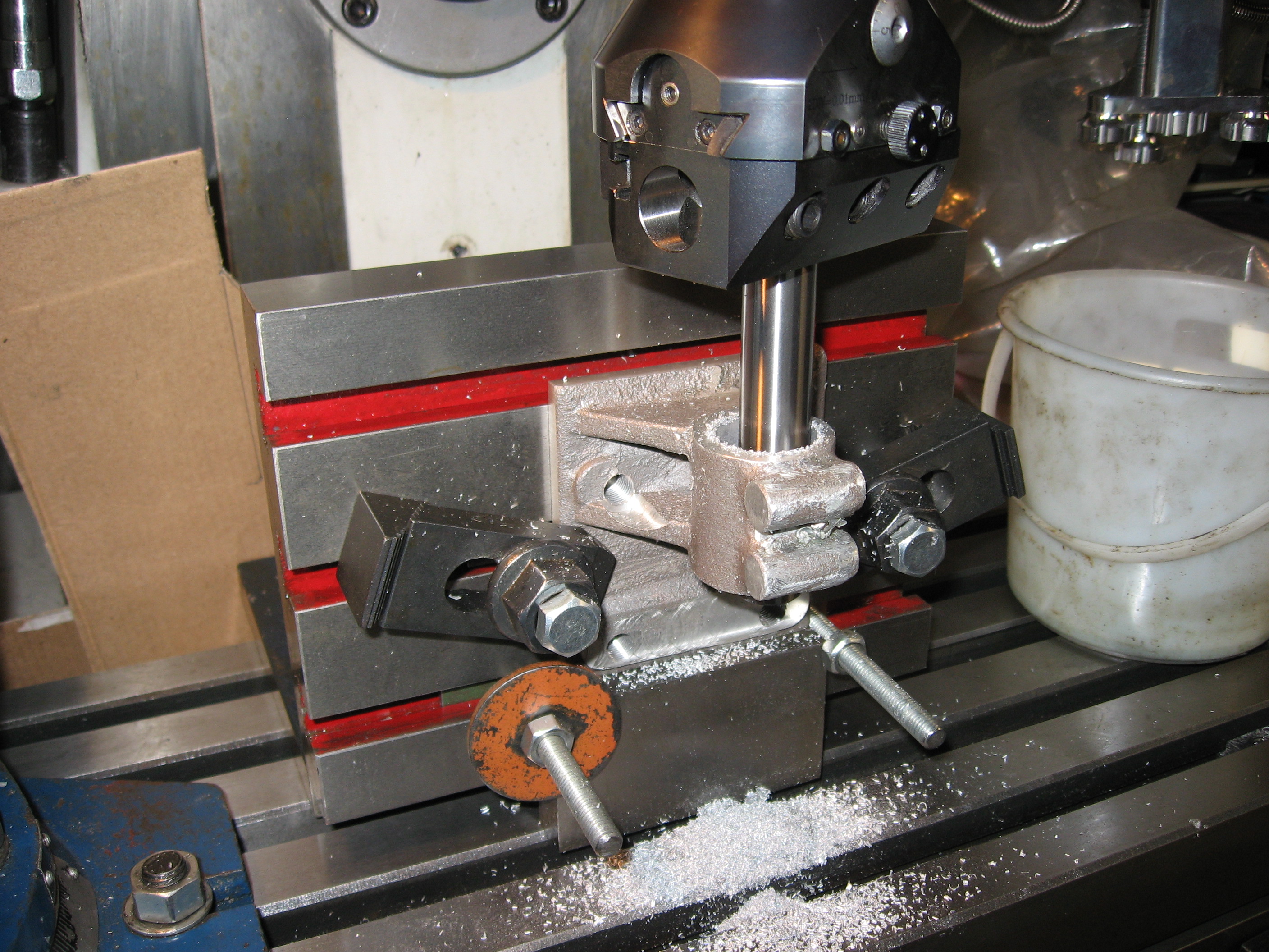
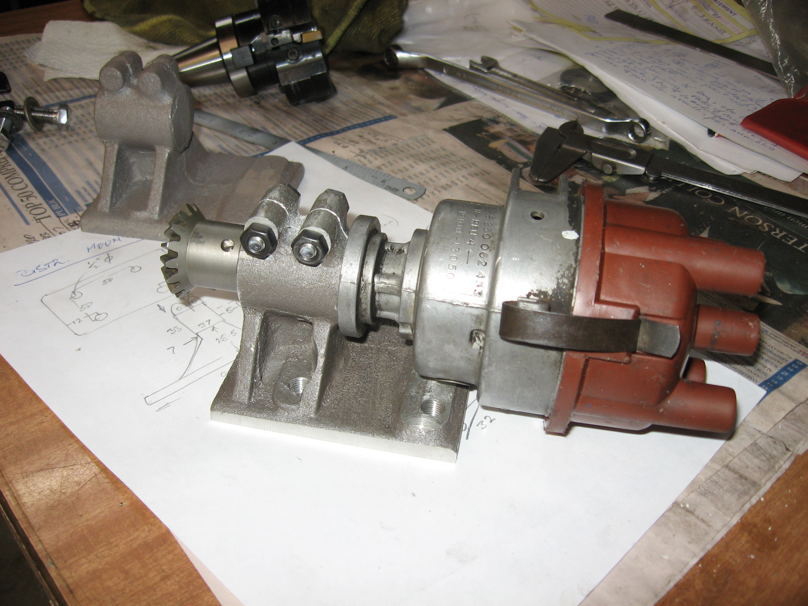
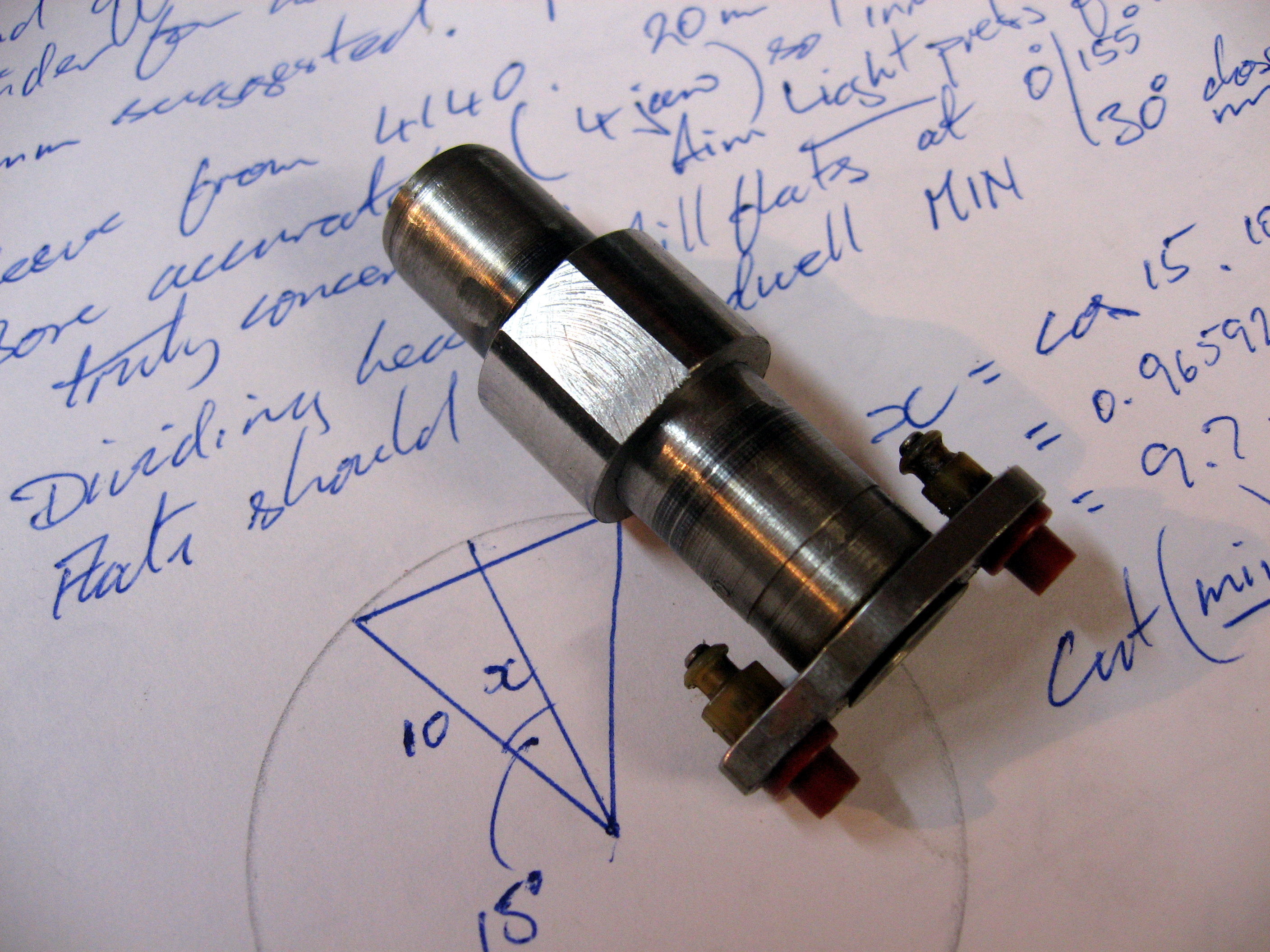
This may be either fabricated from mild steel or cast from aluminium to suit the platform mounting. I chose the latter (because I am a lousy welder). The shaft centre height is 45mm above the platform, and the distributor is 1.062” diameter where it is clamped. See below for machining the 45mm centre height of the distributor and below that for distributor mounted in the bracket:
2. Drive shaft bevel gear.
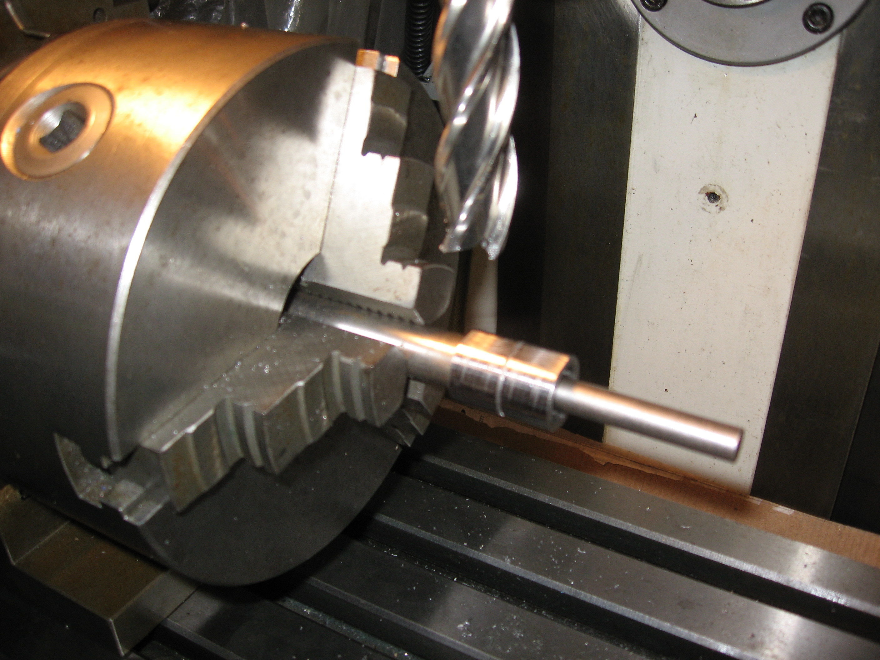
The distributor in its VW life is driven by a skew gear which is a parallel fit on the distributor shaft and pinned in place. The standard JAP bevel gear has a taper seat with no keyway. The choice is therefore to either grind out the taper to fit the shaft or grind a taper on the distributor shaft to fit the gear. It was much easier to have the gear ground to fit the shaft (0.491”) and it can then be drilled and secured with a roll pin to achieve (say) 0.005” end float. It should be a precise but not a press fit on the shaft which would make it difficult to dismantle for servicing; the pin will take all necessary drive load.
3. Cam for points
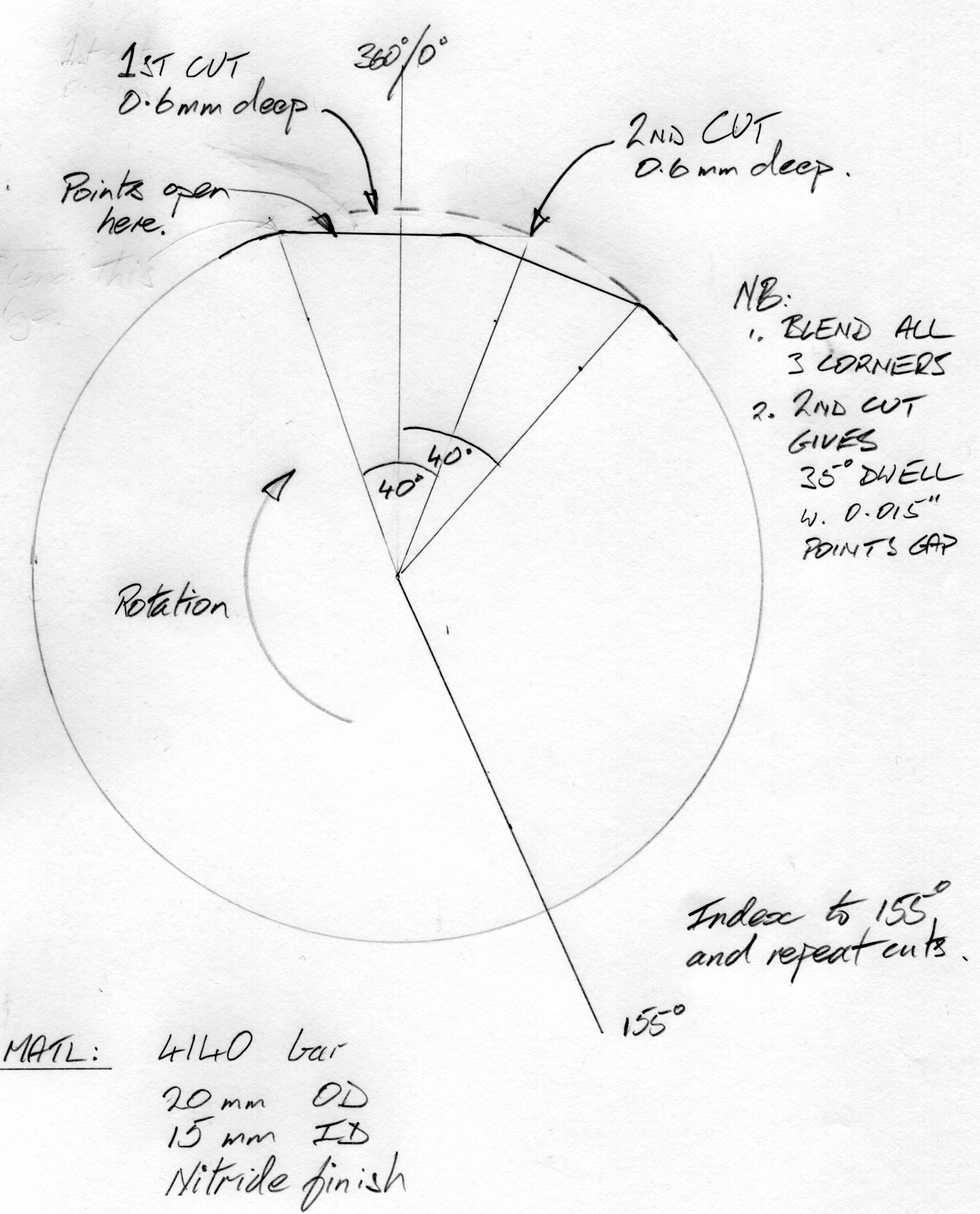
The problem of making an accurate cam is simplified by recognizing that the only critical point is when the points open and a spark is generated. All other points in the cycle can be “more or less”. The dwell time when the points are closed should be not less than 30 deg but could be a lot more, with the only disadvantage being a heavier drain on the battery. The points gap for the rest of the cycle should not be less than .015”.
The Bosch cam is removed by off-hand grinding the hard casing, after which the rotor shaft can be turned accurately with a carbide tip to 15mm dia. A new cam ring can then be machined (below) and fitted to the rotor shaft. The ring has two pairs of flats accurately milled, using a rotary table or dividing head, at 0 deg and 155 deg. The second flat is cut 20 deg ahead of the first to ensure that the points are closed for about 35-40 degree of arc. Importantly, this cut on the leading end of the first cut does not affect the critical point where the contacts open.
 Cutting flats for the new cam-ring
The cam rotates clockwise viewed from the distributor cap end, as shown below. Therefore the points will open at the LH (trailing) end of the flats. Providing that nothing is done to remove metal from this critical contact point you now have an accurate ignition cam for a 50 deg twin.
 Machining details for the pairs of flats
I made the new ring 20mm diameter, which is slightly larger than the diameter of the Bosch cam. Too big a diameter would increase the rubbing speed of the fibre heel of the points. The adjusting slot in the points holder will need to be filed longer to allow correct gap setting with this increased diameter.
In practice it is sensible to lightly stone the edge where the flats and outer diameter of the ring intersect to make life easier for the fibre heel of the contact arm.
 The new cam ring machined and fitted to the rotor shaft.
The new cam ring is made from 4140 steel because it can be nitride hardened, which will be done at a low enough temperature to avoid any distortion. Aim for a light push fit on the shaft so that you can Loctite it in position and this will be enough to prevent it slipping under the friction of the fibre heel. The cam will need to be indexed to the rotor arm so that the rotor is passing a post in the distributor cap as the points open. The rotor is modified as described below to cope with the unequal spacing between cylinder ignition.
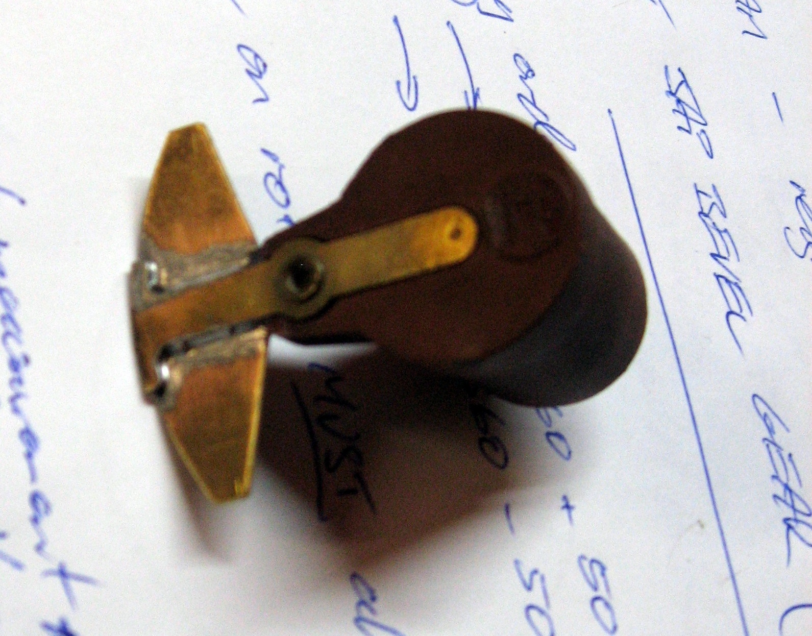
4. Rotor arm.
The standard Bosch rotor arm is retained but modified to extend the arc of the arm (right). This is necessary because the terminals in the cap are spaced for 4 cylinders at 90 rotor degree firing intervals. We are using only two of the (opposing) terminals but the spark will be delivered at 155 and 360 degrees of rotor arc. This is done by soldering a prepared brass segment to the existing arm, but be careful that the extended arm does not foul the terminals in the cap and that the HT spark is not asked to jump Sydney Harbour. Bits of plasticine or BlueTac could serve as a witness to check this. Finally assemble the cam so that the rotor arm is abreast of a contact in the cap at both of the opening points on the cam.
The mechanical advance system is retained and to check the ignition at the desired full advance position grip the rotor arm and rotate clockwise so that the advance weights come up against their stop. Ignition advance is adjusted by rotating the distributor body in the cradle and clamping, which is substantially easier and more accurate than trying to position the bevel gear on the taper and tighten it up after disengaging the magneto.
___________________________________________________________
